


Overview
e-Room Controller 4I/5O Modbus is a fan-coil controller with remote communication, to install in DIN rail cabinets, used for climate and lighting control, managing both systems depending on the occupation state of a room or zone.
The device is specially designed to provide the maximum comfort as possible and an optimal energy saving level of the installation, adjusting the climate control to achieve the value desired by the user.
The device is including different selectable configurations depending on the installation arrangements, and provides a communication bus and output power to supply a user interface based on a visualization display to manage the climate control. A second de-facto standard Modbus communication bus is included on the device to manage remotely the device from the BMS of the building.
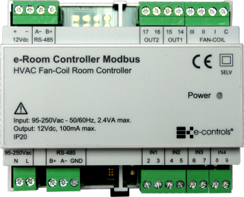
The product is installed with the e-Display device which has some pushbuttons, temperature sensor, and visualization display. The device provides the supply voltage and communication bus to the display. It has some configurable digital inputs for keycard contact or motion sensor, window contact and an analogue input to connect to an external temperature sensor or for door open detection purposes. The controller includes three relay outputs to control the fan coil speed and one or two outputs for cool valve actuator and heating/lighting depending on the device model. The device is directly supplied from mains and is designed to be installed in a DIN rail enclosure.
The product includes a Modbus RTU communication bus to monitor and remote control of the installation, including the necessary registers to configure and manage it throughout an SCADA application. The device is including a configuration table in Modbus for the following operations:
- Configuration of all the parameters of the e-Room Controller and the e-Display.
- Monitoring of the e-Room Controller and e-Display status
- Remote control of the e-Room Controller and e-Display
Main Features:
- Fan-coil controller designed for 2 and 4 pipes installations
- Up to six configurations for similar installation arrangements
- Four self-configurable inputs: Keycard contact/Motion sensor, Window contact, Water temperature (Changeover)/Door contact/Lighting pushbutton, external temperature sensor
- Three relay outputs for fan-coil speeds
- Two relay outputs for valves (2/4 pipes) + room/courtesy lighting
- Modbus RTU communication protocol with RS-485 interface for remote BMS management
- Communication bus with RS-485 interface for display communication
- Mains power supply
- Eco mode on unoccupied zone (Off / ECO set-point)
- Configurable real setpoint and user setpoint for heat and cool
- Automatic switch-on for extreme temperatures (over temp. or frost risk)
- Fan-coil type configuration: 3 speed / 1 speed
- Fan coil speed configurable locked with no demand
- Heat/Cool setpoint in ECO mode
- Configurable heat/cool dead band
- Time to change into stand-by mode when room changes to unoccupied state.
The device can be installed in three different ways:
- Without e-Display interface: For installation like lobbies, common areas, etc. where the ony operation required is through the BMS control.
- With one e-Display interface: This is the most common operation in hotels and offices. The display is installed next to the side bed
- With two e-Displays interfaces: This is an optimal comfort configuration, where one e-Display is installed in the side bed and a second e-Display is installed next to the entrance of the room. Any change in one display or through the BMS is reflected in seconds to the other one device among the Modbus port.
Installation
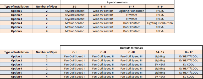
The device includes different operating functions that can be selected depending on the type of installation. The inputs and outputs of the device are automatically reconfigured when the installation type is being configured on the device.
The product is designed for DIN rail installation. It should not be installed on shelves, above or near heat or wet sources, or exposed to direct sunlight.
Important:
- For a correct operating of the system it is necessary to install the device separating the very low voltage wires (inputs) of the mains wires (device supply and outputs) in the cabinet.
- Use shielded wire for the communication bus of the BMS system and the inputs of the device.
- Use the correct wires as specified in the installation drawing of the device.
Caution:
- Prior to installing or removing the device, ensure that there is no mains voltage present in the wiring to be connected or near the unit.
- Do not cut or roll up the wires to be connected to the device.
- Do not work on the wiring with wet hands.
- Do not open or drill through the device.
- Keep the device and the supply wires away from moisture and dust.
- Use a damp cloth to clean the device.
Installation steps:
- Disconnect the supply voltage of the cabinet.
- Open the cabinet and install the device in the DIN rail placing the black clip at the bottom. Pull down the clip and press the device to insert it into the rail. Release the clip and check the device is correctly fitted.
- Verify that all the wires are installed following the constructive mounting diagram provided.
- Check all the wires meet all the specifications and connect them into the female terminals following the installation diagram. Connect the terminals into the device.
- Connect the power supply and verify the correct operating of the device.
- Close the cabinet.
Integration
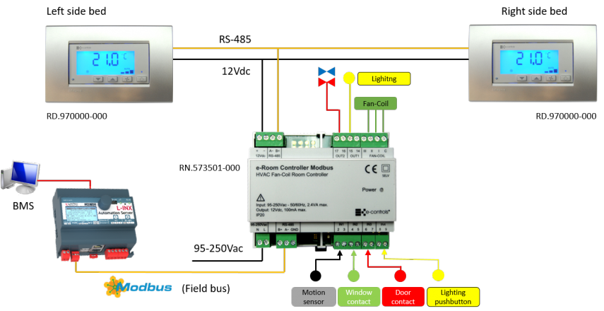
The device includes an RS-485 interface with standard Modbus protocol that makes the device really versatile and easy to integrate in any kind of installation using this protocol.
Through a web server like LINX-102, the device can be integrated in few minuutes thanks to its XML register profile provided by E-Controls with the device.
The drawing shows the possibility to install the device with up to two displays. This is possible thanks to a configuration parameter on the display that allows to install the device with no displays, one or two displays, making it very flexible for any kind of installation.


