


Overview
e-Room® Modbus is a fan coil controller which combine room climate control with lighting control functions, switching on/off those systems depending on the occupancy status of the room.
The device is designed to provide maximum comfort and energy efficiency optimization of the installation, controlling the climate to achieve the desired level by the user.
The device includes different operating configurations depending on the installation type and requirements, as well as a standard Modbus communication bus to communicate with a BMS system.
General Features
- Fan Coil controller designed for 2 and 4 pipes systems
- Six possible configurations depending on the installation type
- Two self-configurable dry contact inputs : Keycard contact / motion detector, window contact
- Two self-configurable analog inputs: Water temperature sensor / Door contact, ambient temperature sensor.
- Three relay outputs for fan-coil speeds
- Two relay outputs for valve actuator (2/4 pipes) + room light / courtesy light
- Modbus RTU communication protocol with RS-485 interface to remote management from BMS.
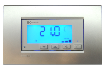
- Large display blue LED backlighted LCD screen of 64x26mm
- Front panel built in pushbuttons: +Tª / -Tª / Fan-Coil speed / On-Off
- Front panel built in temperature sensor
- Selectable temperature units ºC / ºF
- Eco mode on unoccupied zone (Off / ECO set-point)
- Real setpoint and user setpoint configurable for heat and cool
- Automatic switch-on for extreme temperatures (over temp. or frost risk)
- Configurable fan coil: 3 Speeds / 1 Speed
- Fan coil speed configurable as blocked on zero demand
- Configurable setpoint heat/cool temperature on Stand-by mode
- Configurable heat/cool dead band
- Time to change into stand-by mode when room changes into unoccupied state
The device is designed to operate on water installations with 2 or 4 pipes with fan coil and valve actuators to control water flow rates and manage efficiently zone’s temperature.
The occupancy room state can be performed through a keycard contact located in the room (in hotel installations) or throughout a motion sensor and door contact that allows to detected when room changes into occupied or unoccupied state.
The device provides a configuration parameter to switch off the climate or change into economic mode modifying the temperature set point to a pre-set value for energy saving, when room changes into unoccupied state.
An input contact to manage the window status allows to switch the climate off when the window is open, saving energy during that period of time, and switching the climate on again when the window closes.
Depending on the type of installation configured, the device can control zone lights, switching it on automatically when room changes into occupied state and switching it off when room changes into unoccupied state. Additionally, the light control can be configured as a courtesy light for hotels installations. In that case, lights will switch on during a preconfigured time and then will switch off when room changes into occupied or unoccupied state.
Installation
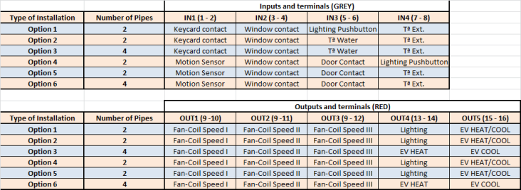
The device includes up to 6 different operating modes according to the installation type. Device inputs and outputs are used to perform room or zone automation depending on the type of installation set up. Depending on the configured operating mode on the device, each input and output have a specific functionality according to normally operating requests of installations.
Refer to the “Operating manual” of the device for additional information about the product functionality.
This device should not be installed on shelves, behind curtains, above or near heat sources, or exposed to direct sunlight. For fast and accurate ambient temperature measurement, the controller should be installed such that air may circulate vertically. Installation height should be approximately 1.5 m from the floor.
Caution:
- Prior to installing or removing the device, ensure that there is no mains voltage present in the wiring to be connected or near the unit.
- Do not cut or roll up the wires to be connected to the device.
- Do not work on the wiring with wet hands.
- Do not open or drill through the device.
- Keep the device and the supply wires away from moisture and dust.
- Use a damp cloth to clean the device.
Installation steps:
1º Install the flush mount back box on the wall
2º Connect all wires to the appropriate device terminals ensuring that there isn’t voltage on it, following the wiring diagram.
3º Insert and screw the device in the box
4º Fit the frame onto the device
5º Remove the front panel anti-scratch protective foil
Integration
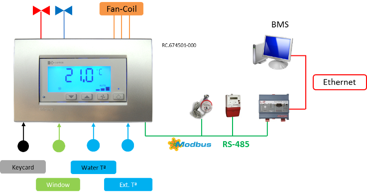
The device has an RS-485 communication interface to communicate through the standard Modbus RTU protocol, and throughout which is possible to enter to each configuration parameter, monitoring different device parameters like room’s temperature, occupancy state, fan coil speed, etc. and remotely switch it on, change temperature set-point or modify whatever parameter on the device.
The device includes 36 configuration parameters that can be modified to adapt the operating functions of the device to the installation requests. All that parameters are configurable through a simple configuration menu entering using the pushbuttons included on the front panel of the device or remotely throughout communication bus.


