


Overview
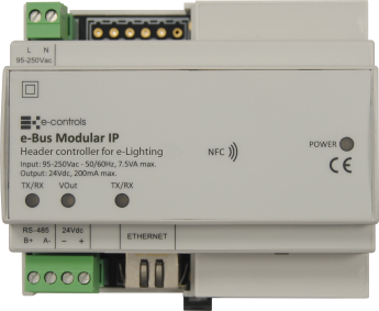
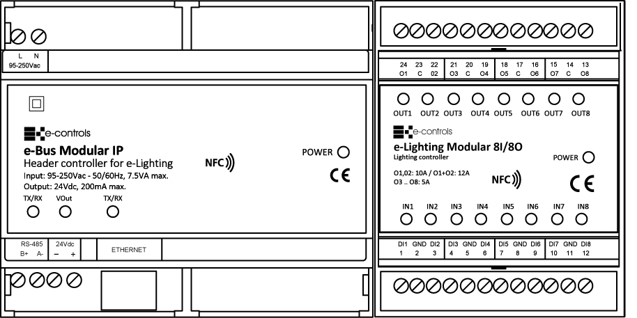
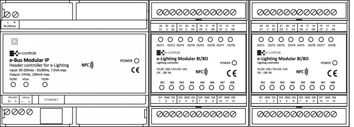
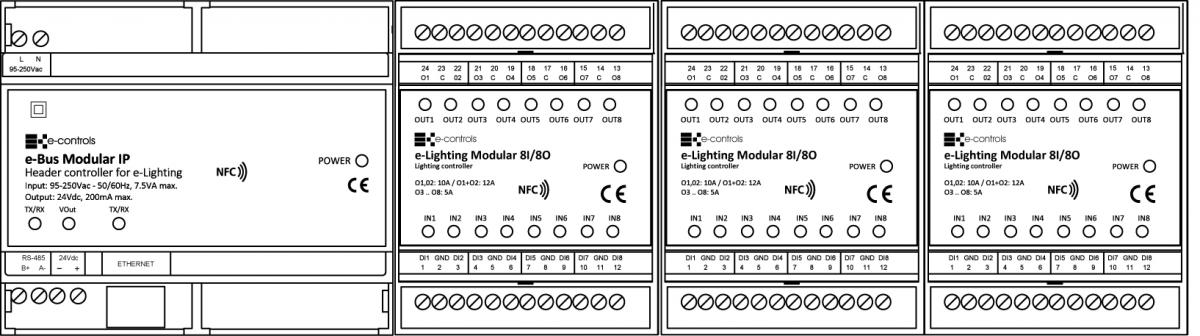
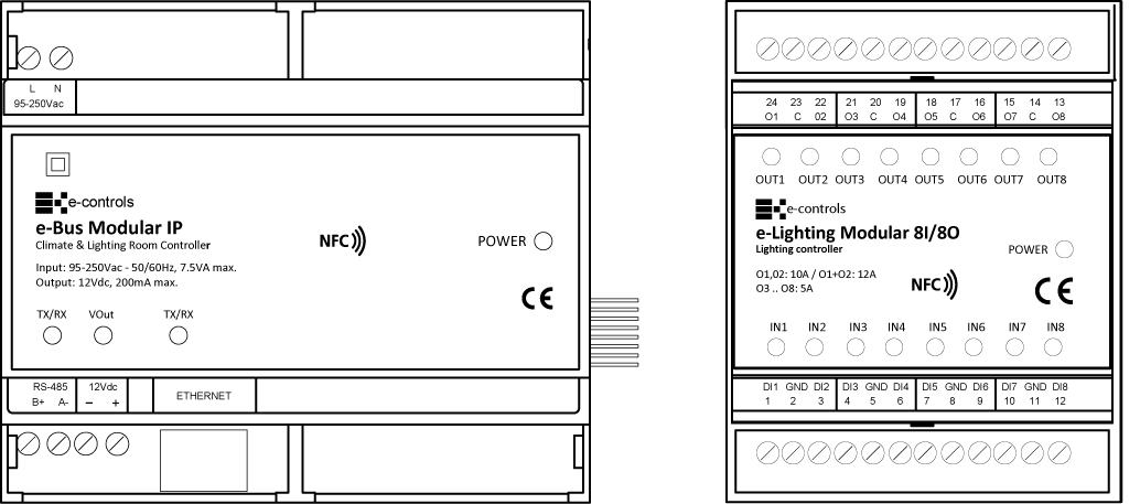
e-Bus Modular IP is a controller for e-Lighting devices that has a communication port to monitor the inputs status and actuate remotely over the outputs of the devices connected to it. The device has an Ethernet port to connect to the structured wiring of the building to be able to remotely control the e-Lighting devices over the Modbus TCP protocol. The device has a side connector called “Modular Bus” through which up to 3 e-Lighting devices of any input/output configuration can be connected.
1) Configuration with 1 e-Lighting Modular module
2) Configuration with 2 e-Lighting Modular modules
3) Configuration with 3 e-Lighting Modular modules
It also has several led indicators to signal the inputs and outputs status, and an NFC interface through which it is possible to configure several parameters of the device, like the IP address, using the EConfigurator APP for mobile phone with Android operating system.
Click on this link from a mobile phone or from a tablet with Android operating system to download the EConfigurator APP.
Through the communication bus of the e-Bus Modular unit, it is possible to access the status of the inputs and outputs and act on the outputs of the e-Lighting equipments that are connected through the "Modular Bus" side connector. For this, a map of Modbus registers that allows access to all the configuration parameters and input and output registers of the equipment is available.
Device configuration
The device can be configured through the Modbus communication port accessing to the configuration registers, or through the wireless NFC interface and the EConfigurator APP. Configuration through the NFC interface can be done with the device plugged or unplugged, facilitating the maintenance tasks. If the applied configuration does not match the connected devices, the power led with light up in orange colour.
An operating system in the device allows the possibility to update the device with new software versions through the ethernet port, using an application provided by E-Controls.
The device has a label with the purchase product reference, the serial number and the MAC IP address.
Installation
To connect e-Lighting equipment to e-Bus Modular, use a side connector supplied with the equipment:
The product is designed to be installed in a DIN EN 60715 cabinet. It must not be installed over shelves, behind curtains, over or near to heat sources or exposed to direct solar radiation.
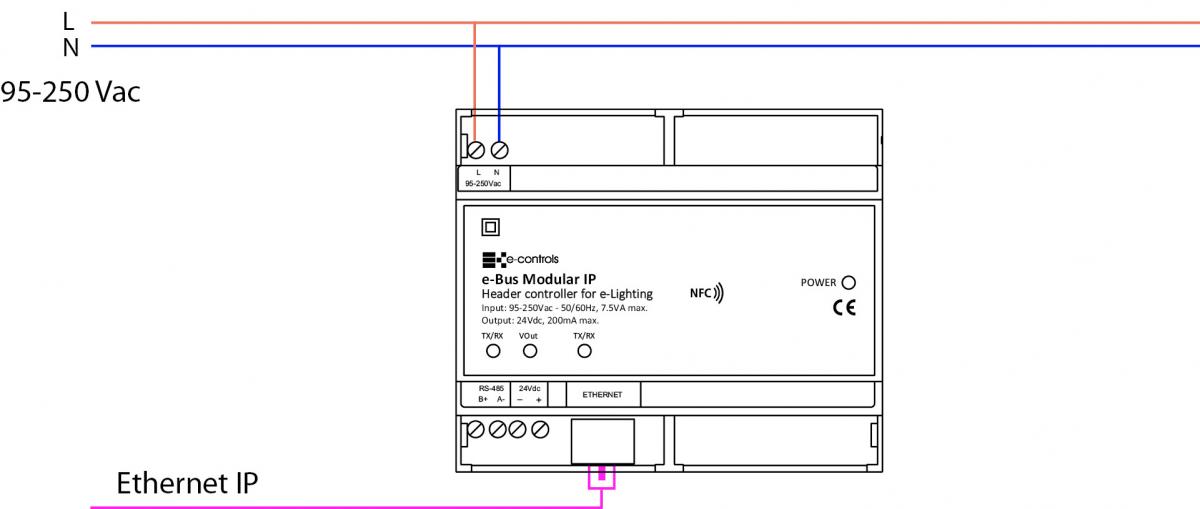
Installation drawing:
Important:
- For a correct operating of the system it is necessary to install the device separating the very low voltage wires (inputs) from the mains wires (device supply and outputs) in the cabinet.
- Use shielded wire for the communication bus of the BMS system.
- Use the correct wires as specified in the installation drawing of the device.
Caution:
- Before installing or removing the device, make sure that there is no mains voltage present in the wiring to be connected or near the unit.
- Do not cut or roll up the wires to be connected to the device.
- Do not work on the wiring with wet hands.
- Do not open or drill through the device.
- Keep the device and the supply wires away from moisture and dust.
- Use a damp cloth to clean the device.
Installation steps:
- Disconnect the supply voltage of the cabinet.
- Open the cabinet and install the device in the DIN rail placing the black clip at the bottom. Pull down the clip and press the device to insert it into the rail. Release the clip and check the device is correctly fitted.
- Verify that all the wires are installed following the constructive mounting diagram provided.
- Remove the side label to connect the e-Lighting devices to the unit.
- Connect the power supply and verify the correct operating of the device.
Integration
The device has a Modbus register map with all the registers necessary to configure, monitor and control the e-Lighting devices that are connected to the unit. The Modbus map of the device is divided in three parts:
- Configuration registers
- Input registers
- Output registers
Through these registers it is possible to configure the device, to know the state of the inputs and actuate over the outputs of the e-Lighting devices. The device can control up to 3 e-Lighting devices of any combination of inputs/outputs.


