Overview
The e-Room Modular ECO is a DIN-rail mounted controller designed for fan-coil EC (0-10V) control units and On/Off valve control. The device includes a Modbus communication port, enabling integration and remote control from a BMS system.
It features pre-programmed operating modes for both 2-pipe and 4-pipe installations, as well as an additional relay output for lighting control linked to the selected control logic. A wide range of configuration parameters allows full adaptation of the device to the requirements of each project.
The four digital/analog inputs enable the implementation of energy-saving functions in the conditioned zone:
• Occupancy input through a keycard contact.
• Window contact input, which stops climate control when the window is opened.
• Combined inputs for motion detector and door contact, allowing automatic occupancy detection in hotel rooms.
Configuration of the device can be performed using the E-Configurator mobile application via the NFC interface, with or without power supply, or through Modbus registers. In installations with a display, configuration can be performed through the display’s NFC interface, which automatically transfers the data to the controller. In installations without a display, the NFC configuration is applied directly to the controller, requiring a temperature sensor connected to input IN4 or a temperature value sent via Modbus for temperature control. In both cases, all parameters — both of the display and of the controller — can be modified via the Modbus communication port of the e-Room.
The unit is mains-powered and designed for DIN-rail cabinet installation.
Main Features Summary
- Fan-coil controller for 2-pipe or 4-pipe installations
- Two self-configurable dry contact inputs: keycard, window contact
- Two digital/analog NTC10K inputs for multiple functions: door contact, water temperature, room temperature
- One analog 0-10V output for fan-coil EC speed control
- Two relay outputs for valves (2-pipe / 4-pipe systems or auxiliary output in 2-pipe mode)
- One auxiliary relay output for lighting control
- RS-485 communication bus for connection with thermostat display
- Mains-powered device for DIN-rail installation
- Configurable Economy mode when the room is unoccupied (off / setpoint change)
- Configurable fan-coil type: 3-Speed / 1-Speed
- Configurable fan-coil interlock speed when there is no demand
- Configurable heating/cooling setpoint temperature in ECO mode
- Configurable dead band between heating and cooling
- Adjustable delay time to enter standby mode when the room becomes unoccupied
This table summarizes the pre-programmed operating modes and the function of each input and output of the device for every mode.
Refer to the document “Configuration Manual” of the device, which describes the configuration parameters and the procedure to modify the predefined parameter values.
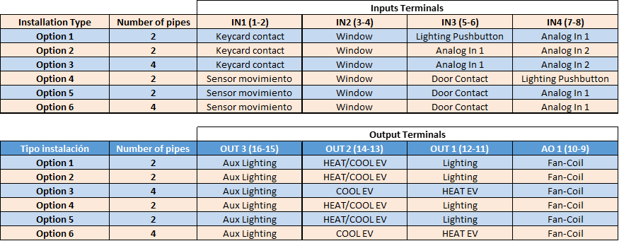
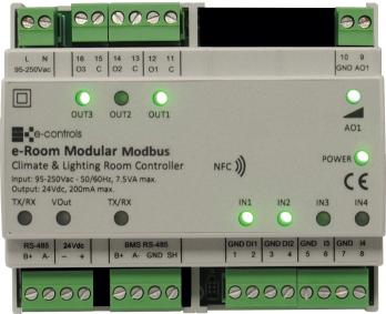
IN1, IN2: Digital Inputs - IN3, IN4: Digital/Analog (NTC10K) Inputs
AO1: Analógica 0-10V Output, OUT1, OUT2, OUT3: Relay Outputs
Installation
The device is designed for installation in cabinets with standard EN 50 022 DIN rail mounting. It must not be installed on shelves, behind curtains, near or above heat sources, or exposed to direct sunlight.
Important:
- Install the device inside the electrical panel, keeping extra-low voltage signal wiring (inputs) separated from low voltage wiring (outputs).
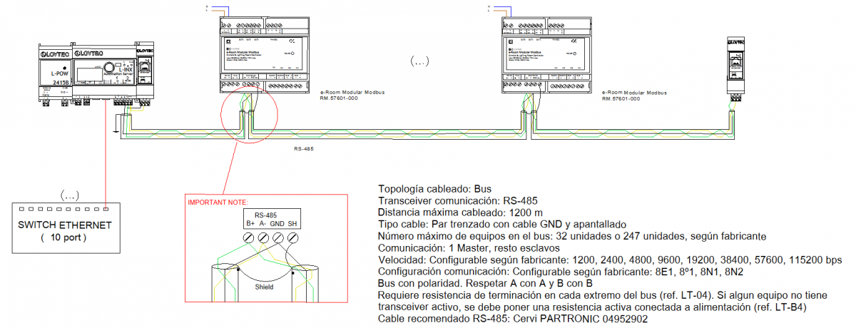
- Use shielded cable for the communication channel with the BMS.
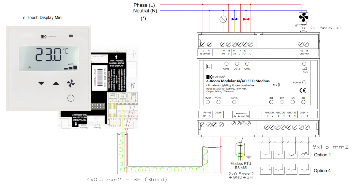
- Always follow the wiring type indicated in the installation diagram.
Precautions:
- Before installing, removing, or cleaning the device, ensure that no mains voltage is present on the cables or near the device.
- Do not cut, splice, or coil the mains cables connected to the device.
- Do not handle connections with wet hands.
- Do not open, drill, or modify the product.
- Keep the device and cables away from moisture and dust.
- Clean only with a slightly damp cloth using water.
Mounting Steps:
- Disconnect the power supply of the electrical panel.
- Insert the device onto the DIN rail with the black latch positioned at the bottom; pull the latch downward, press the device until it clicks into place, and release the latch to secure it.
- Verify that the panel wiring follows the installation layout diagram.
- Connect the cables to the terminals according to the wiring diagram and attach them to the device.
- Restore power supply and check proper operation.
- Close the electrical panel.
Integration
The device includes an RS-485 communication interface that operates using the Modbus RTU standard protocol. Through this interface, it is possible to access all configuration parameters of the device, monitor various operating variables such as room temperature, occupancy status, or fan-coil speed, and remotely control the unit to activate it, change the temperature setpoint, or modify any other available parameter.
The device provides multiple configuration parameters that allow the product to be adjusted to the specific needs of each installation type. All these parameters can be configured through a simple configuration menu accessible from the device’s front keypad and display, or remotely via the communication bus.