


Overview
e-Bus Coupling is a family of multiprotocol intelligent coupling units that are connected to the e-Touch Flexi touch panels, to provide a communication protocol or also different inputs and outputs to perform a control solution over a lighting system, management of scenes, blinds or curtains automation or any other control required in the installation.
Different models of coupling units e-Bus Coupling device are available: some models with communication protocol to integrate into a BMS control system, and some others with physical inputs and outputs to manage a control system.
For lighting control different models are available for digital lighting control with the standard DALI protocol, but also with analog control and 0-10V output, that provide all the functions required for a lighting control solution, like switching on and off, manual dimming and scene management. For any other control, different models with the most used communication protocols of the market are available and provide a way to transfer data with a BMS control system or homes.
e-Bus Coupling has an standard format that can be installed in a universal 66x66 mm wall mount enclosure and includes some holes at 60x60 mm to fix into standard enclosure.
Product application:
- Bus coupling unit for e-Touch Flexi and e-Touch Panel touch switches.
- Slave device: A DALI 2 controller on the bus is required
This model is powered directly at mains, to avoid consuming current of the DALI bus, and is a device that requires a DALI gateway or controller as a master unit, that will execute the messages sent by every touch switch+bus coupler to the communication bus.
The device is compatible with any of the e-Touch family products, and is automatically configured according to the number of touch zones or buttons of each touch panel. Each touch switch has a predefined number of touch zones and Led indicators with a different arrangement (for more information read the instruction sheet of each touch switch). According to the DALI 2 protocol, this device is identified as an IEC62386.304 Push Button device with a number of instances equal to the number of touch zones of the touch switch connected.
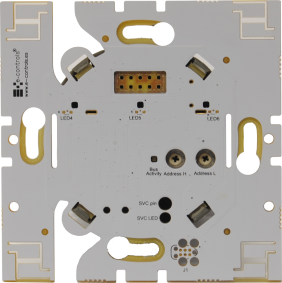
Digital inputs
The device has two digital inputs of dry contact type, to connect any sensor or device with a free potential contact output to do an additional management with the keypad, like a motion sensor, a window contact, etc. Both inputs will be seen in the software application of the DALI controller as the two last instances of the device, being IN1 the instance “n-1” and IN2 the instance “n”. In order to see these instances, an e-Touch switch device must be connected previously to the coupling unit.
“State” Led indicator
The device has a led indicator in front of it marked as “State” that indicates the operating state of the device. When the touch switch is not connected to the bus coupling unit , the led indicator flashes every 5 seconds, indicating that it works correctly. When powering the device and the bus coupling unit has detected a touch switch connected to it, the led indicator will light up during 2 seconds and then will blink when transmitting or receiving DALI messages. This sequence can be seen if the touch switch is mounted temporarily without the frame.
“SL” Led indicator
The device has a led indicator in the side of the box, marked as SL, that shows the DALI bus activity.
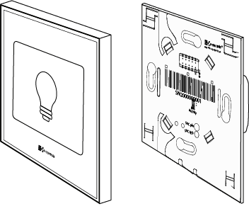
Installation
Installation drawing of the product

Product assembly
The device is installed in a universal flush mounting enclosure or also in a plasterboard enclosure, plus any touch switch of the e-Touch Flexi or e-Touch Panel family products.
Read carefully the installation steps of the device explained in the instruction sheet.
Important:
- In order to do the e-Bus Coupling DALI operational, any e-Touch Flexi or e-Touch Panel device must be connected to the device.
- Follow the recommendations of the DALI standard for the wiring installation in the building.
Mounting steps of the device:
- Disconnect the DALI supply power and the mains power to which the device wants to be installed.
- Connect the DALI wiring and the mains following the installation drawing. The DALI bus does not have polarity.
- Fix the device to the enclosure with the screws. If an e-Touch Panel is going to be used, fix also the adapter provided with the touch switch, inserting the two notches of the adapter to the frame, so that the touch switch can be clipped with its four ends.
- Assemble the plastic frame on the touch switch paying attention that the ventilation slots are in the lower and upper left side.
- Insert the e-Touch Flexi or e-Touch Panel into the holes of the front connector on the bus coupling unit, until the white clips of the touch switch match the ones of the bus coupler, and press until the frame will be firmly fixed to the wall and pressed by the keypad.
- Apply power to the DALI bus and check that any of the blue leds of the touch switch blinks.
- Proceed to configure the device according to the steps defined in the “Configuration” section.
Caution:
- Disconnect the power supply before mounting or moving the device.
- Do not leave cables peeled or turned around the device.
- Do not connect the device with the hands wet.
- Do not open or hole the device.
- Keep the device and cables away from humidity and dust.
- Clean the front cover with a water moisture soft cloth.
Integration
IMPORTANT: Before starting the configuration process, check that a touch switch is connected to the device.
Once the device is installed, start commissioning it in the DALI bus. To do this, launch the “scan” function in the software application of the DALI gateway/controller previously selected. When the “scan” function has finished, all the e-Bus Coupling units with a touch switch connected, will appear in the application. Then, proceed to commission the device according to the application of the DALI controller manufacturer.
For more information regarding the configuration of the device, read the instruction sheet of the e-Touch Flexi or e-Touch Panel touch switch.
Identifying the device in the DALI bus
The “wink” command of the DALI protocol is used to identify the device during the commissioning process. Upon receiving this command, the led indicator number 1 of the touch switch will blink during 30 seconds.
Changing the touch switch by another model
In case it is necessary to change the touch switch configured, by another model, a reconfiguration process must be done. To do this, unconfigure the bus coupling unit from the DALI controller (Unassign function), disconnect the DALI supply power, remove the touch switch and connect the new model, apply power supply again, and start again the configuration process (Scan).
NOTE: The replacement of one touch switch by another one of the same model does not require any reconfiguration.


