


Overview
AirQualy is a family of sensors designed to measure the quality of air in buildings. The product is available in different models which include a combination of Temperature, Humidity, CO2, Volatile Organic Compound (VOC) and Particulate Matter (PM) sensors and is available in two formats: One with LED indicators in different colours that switch on in accordance with the value measured by each sensor; and the other without LED indicators, for cases in which the purpose is to send the information to a controller or building management system (BMS).
The AirQualy T + HR + PM model includes 3 different sensors to measure temperature, humidity and Particulate Matters (PM) to measure particles of size 1 micron, 2.5 microns, 4 microns and 10 microns. The equipment is available in two finishes: a model with 3 columns of LED indicators to signal the measurement of each sensor. The PM measurement is displayed in one columns with 5 LED indicators and the temperature and humidity measurements are displayed in two columns with 3 LED indicators each. There is a second model without LED indicators. For a correct CO2 measurement, we recommend installing a sensor every 30 m2.
The unit is made up of two elements that provide a large number of combinations and are purchased separately: the AirQualy front panel, which includes the sensors, the LEDs, the frame and a sample label; and the “e-Bus Coupling Surface” mechanism, which provides the power supply and the type of control output. It is available in three models: an stand-alone model without outputs, a model with a relay output and 0-10 V / 4-20 mA outputs which can be configured in order to provide the measured value or perform direct control of a damper for air renewal. There is a third model with Modbus communication to integrate into a building management system (BMS).
The product is configured by means of the EConfigurator APP with a smartphone and the information is wirelessly transferred to the unit via NFC.
The equipment has multiple applications to measure air quality in building environments such as:
- Schools
- Hospitals
- Offices
- Hotels
- Commercial areas
General features:
- Sensor for Temperature, Humidity and Particulate Matter
- Factory calibrated and long-lasting (>10 years)
- Four columns of LED Indicators to show the value of the measurement
- Wirelessly configured via NFC with the APP EConfigurator
- Display of the measured values through the ETools APP
- Surface mounting with two screws
- Three types of output for control: stand-alone (no outputs), with an 0-10V / 4-20 analog output and one relay, with Modbus communication
- PI control for direct management of an air renewal damper, door opening, etc, according to the chosen e-Bus Coupling Surface coupler
- 12-24 Vdc supply power with external power supply
Product models:


Model without LED indicators Model with LED indicators
LED indicators to display the measured value
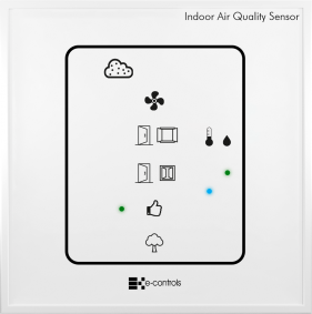
The equipment includes 5 LED indicators (blue, green, yellow, orange and red) to display the CO2 level, from best to worst air quality. Each LED is associated with a range of values and lights up when the measured value is within its range. The temperature and humidity measurements are represented by three LED indicators. If the measured value is within a predefined range, the green LED turns on, if it is above the range, the red LED turns on and if it is below the range, the blue LED turns on.
Indicadores led para visualizar el valor medido
La medida del sensor de PM se representa a través de 5 indicadores led de colores azul, verde, amarillo, naranja y rojo, que muestran los niveles medidos de mejor a peor calidad de aire. Cada led está asociado a un rango de valores y se ilumina cuando el valor medido se encuentra dentro de su rango. Las medidas de temperatura y humedad se representan a través de tres indicadores led. Si el valor medido se encuentra dentro de un rango predefinido, se enciende el led verde, si está por encima del rango, se enciende el led rojo y si está por debajo del rango, se enciende el led azul.
Through the EConfigurator APP (see configuration section) it is possible to modify the range of values associated with each LED indicator and sensor to adapt them to the needs of each installation.
Viewing values through a mobile phone
The measured value of each sensor can be viewed with a mobile phone via the NFC interface. To do this, you must download the ETools APP from the Play Store and install it on a mobile phone with an Android operating system.
Calibrated sensor
The sensor included in the equipment is factory calibrated and has high precision and an extended measuring range (see product datasheet). The PM sensor includes MCERTS certificate.
Design your own product
The front panel of the unit includes an interchangeable label (E-Controls patent) with texts and icons that can be designed in accordance with the needs of each project by means of the e-Touch Creator web application. The equipment is supplied with a label that includes the aesthetics of the product shown on this web page. If you want to design your own label, register on the website and click here to access the application.
Equipment setup
The equipment is configured through a mobile phone using the E-Controls EConfigurator APP and NFC proximity wireless data transfer technology. To do this, you must download the APP from the Play Store and install it on a mobile phone with Android operating system and download the project by placing the phone on top of the front until the device’s antenna is detected. Once the phone has detected the equipment, download the project by pressing the data transfer icon in the APP. For more information, please refer to the operating manual of the EConfigurator APP.
In the model with Modbus coupling unit it is also possible configure the device via bus. The configuration manual details all the parameters available on the equipment.
The device configuration can be done without powering the equipment, and even without removing it from the packaging box, thus greatly facilitating the configuration process.
Installation
IMPORTANT NOTE: Install the equipment at a height equal to or greater than 150 cm from the ground. The equipment can react more quickly depending on the speed of the air around the sensor. Avoid installing the equipment near an air outlet with a concentration of CO2 and dust.
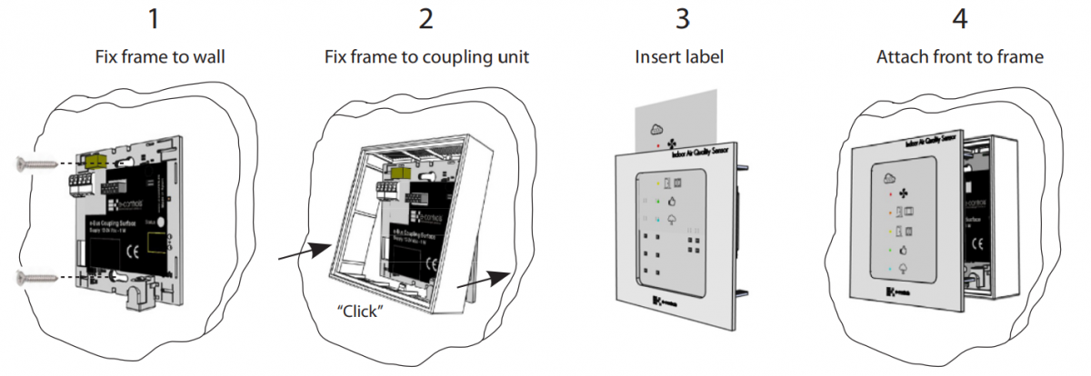
Product assembly process
- Insert the label in the upper slot on the front of the equipment.
- Fix the e-Bus Coupling Surface rack to the wall. If the equipment requires external or bus power supply, connect the cables to the corresponding terminals (see e-Bus Coupling Surface Instruction Sheet).
- Fix the frame to the rack by lightly pressing on the lower and upper part until you hear a "click".
- Attach the front centred on the frame.
- Power the equipment and wait 5 minutes to obtain a correct measurement.
Product disassembly
- Insert a small screwdriver into the window located at the bottom of the frame. Slightly pry out with the screwdriver and remove the frame from the bottom.
- Slightly move the frame upwards and completely remove the front and frame.

Integration
If you want to integrate the equipment into a BMS building management system, you need to choose one of the existing "e-Bus Coupling Surface" couplers.
See the e-Bus Coupling Surface section to select the appropriate model.


