Overview
e-Bus Coupling Surface is a family of smart mechanisms that are connected to AirQualy sensors to supply them with the power they need to operate. Depending on the model, they include a communications protocol to transmit the information to a building management system or a range of digital and analogue outputs to control an air renewal system.
There are three models to choose from in accordance with the needs of each installation: a stand-alone model, a model with outputs 0-10V / 4-20 mA and relay, and a Modbus model.
The e-Bus Coupling Surface Modbus model has Modbus RTU (RS-485) communication with multiple registers to configure the Modbus address, communication speed and parity, setpoints of each sensor to perform a control, measurement levels for each led indicator and each sensor, and output registers to send instantaneous sensor values and filtered values. The equipment also includes an output register that provides PI control of any sensor.
The unit is designed to be mounted on a surface. Therefore, it is not necessary to use a box for its installation, given that it can be installed on any wall or glass surface.
General features:
- AirQualy sensor mounting frame
- Modbus RTU communication (RS-485)
- Configuration through AirQualy sensor with APP EConfigurator by NFC
- Configuration registers, input and output
- Surface mounting
- Supply power 12-24 Vdc
The e-Bus Coupling Surface Modbus equipment is responsible for providing the necessary power to the AirQualy sensor for its operation. This product model has a Modbus communications bus through which it is possible to configure all the equipment, read the values of all the sensors through output registers and work on the equipment through input registers. The equipment includes a Proportional Integral (PI) control system to carry out direct control over an output module and work on an air renewal damper or an air conditioning system. To this end, the equipment has registers to configure the control setpoints and adjust the PI control algorithm with the Kp and ti parameters.
The following graphs show the operation of the PI control:
a) Response register output outPI_control:
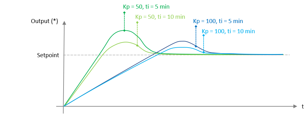
b) Kp transfer graph:
![]()
Equipment setup
This product model can be configured through the Modbus communication por or laos through the AirQualy front, using the E-Configurator APP. When creating the project in the APP, select this product model. When the project opens, click on the device bar and select the coupling unit to modify its configuration parameters.
Installation
Led indicator of operation
The equipment includes a LED indicator on the front called Status that has the following statuses:
- Normal operation: When the equipment is powered, it turns ON and after a few seconds it goes OFF
- Air Qualy disconnected: The LED briefly flashes every two seconds
- Configuration fault: This fault occurs if the AirQualy front panel has been configured with a different frame than the one it was connected to. In this case the LED flashes every seconds
- AirQualy internal fault: The LED lights up for more than 6 seconds
- Software download: The LED lights up fast
Mounting process of the product
The equipment is designed to mount directly on the surface, fixing the holes in the equipment with 2 screws. The AirQualy front frame acts as a product box, being protected once it is fully installed.
The cables connecting to the equipment must not have a section greater than 0.5mm.
Installation process
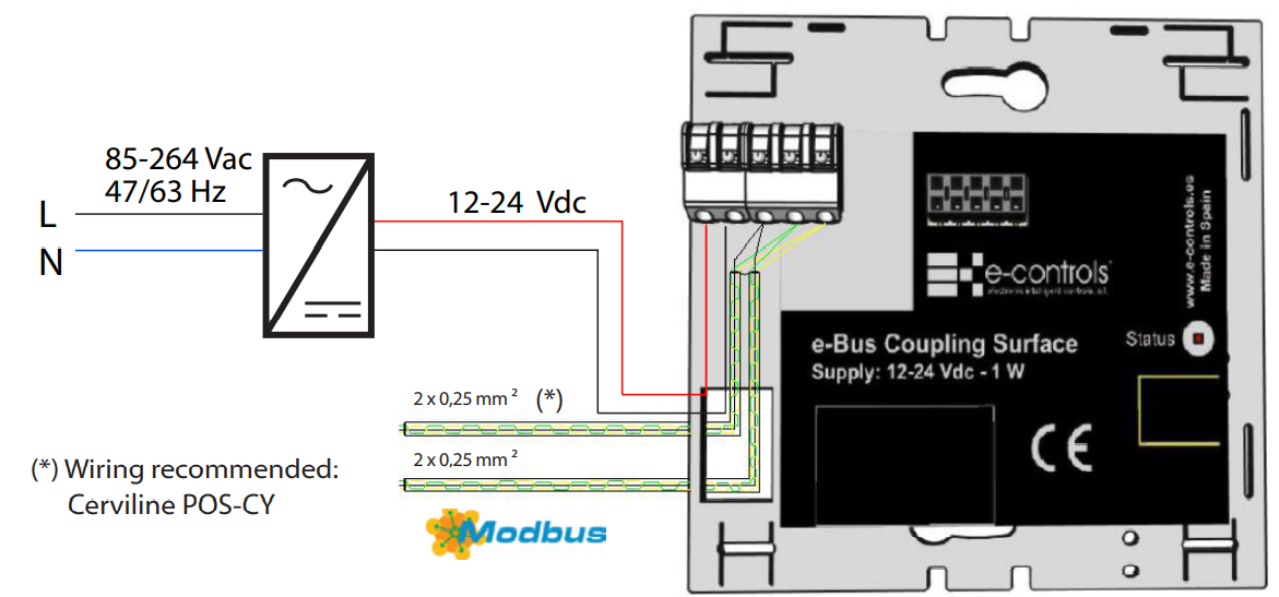
- Pass the power supply and output cables through the hole in the coupling unit (see installation diagram).
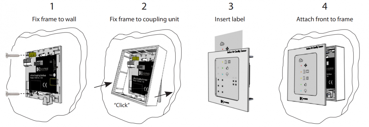
- Fix the e-Bus Coupling Surface device to the wall.
- Fix the frame to the coupling unit fixing it on the upper part and pressing lightly on lower part until you hear a “click”.
- Insert the AirQualy sensor centred on the frame, previously inserting the label supplied with the sensor, in the front of the equipment.
- Power the equipment and wait 5 minutes to obtain a correct measurement.
Installation diagram